-
Capacitive sensor
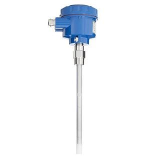
NivoCapa® - NC 8100
Medium Liquids Process pressure -1 bar … +35 bar (-14.5 psi … +511 psi) Process temperature -40°C ... +200°C (-40°F … +392°F)
with capacitive measurement technology
To explain capacitive level measurement technology, it is important to understand the basic principle of a capacitor. A capacitor consists of two conductive electrodes insulated from each other. It has the ability to store energy between its electrodes within an electric field. If non-conductive material (= the dielectric Ɛr) gets between the electrodes, the amount of storable energy increases and thus the capacitance of the capacitor. This is additionally determined by the dimensions of the electrodes (area A) and their distance (d) from each other. The capacitance of a plate capacitor is generally described by the formula C = Ɛr * A/d.
With this understanding, the operation of a can now be explained. This consists of a medium-contacting metallic probe (rod or cable) which, together with a conductive container wall, can be understood as the two electrodes of a capacitor. A non-conductive medium, such as oil (non-conductive media < 1 µS/ cm), forms the dielectric between these two electrodes. If the level now rises, the electrode area increases, which in turn leads to an increase in capacitance. This change in capacitance is detected by the sensor and converted into a signal proportional to the level.
Due to their function, capacitive level sensors often have to be adjusted and calibrated to the medium (empty and full capacitance). The medium adjustment is not necessary if the medium to be measured is conductive, such as water (conductive media > 100 µS), since in this case the medium itself represents the second electrode. The insulating PFA rod sheathing serves as dielectric, whereby the basic principle of a capacitor is given again.
FAQs
Where can capacitive level sensors be used?
The NC8 capacitive level sensor is suitable for:
- Liquids
- Applications with condensate formation
- Very strong caking
- Aggressive materials due to its corrosion resistance
- High safety standards
- Potentially explosive areas